REMOVAL


6 - Locating Pins
Six individual, solenoid actuated high-pressure fuel injectors are used. The injectors are vertically mounted into a bored hole in the top of the cylinder head. This bored hole is located between the intake/exhaust valves. High-pressure connectors, mounted into the side of the cylinder head, connect each fuel injector to each high-pressure fuel line.
1. Disconnect both negative battery cables from both batteries. Cover and isolate ends of cables.
2. Remove breather assembly.
3. Remove valve cover. Refer to Engines for procedures.
4. Remove necessary high pressure fuel line connecting necessary fuel injector rail to high pressure connector.
5. A connector retainer is used on each connector tube. Remove this nut(s) by unthreading from cylinder head.
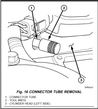

6. Using special high-pressure connector removal tool # 9015 remove necessary high-pressure connector(s) from cylinder head. Tool # 9015 threads onto connector tube. Use tool to pry connector tube(s) from cylinder head.
7. Remove necessary exhaust rocker arm assembly(s).

4 - Passthrough Connector
8. Disconnect injector solenoid wire nuts at top of injectors (Fig. 18).
9. Remove 2 fuel injector hold-down clamp bolts at each injector being removed.
10. USING TOOL # 9010:
- Special Tool # 9010 (Fig. 19) is equipped with 2 clamshell clamps, a sliding retainer sleeve to retain the clamshell clamps, a 2-piece mounting stud, and a pivoting handle. Do not attempt to remove the fuel injector with any other device. Damage to injector will occur.
- The rocker housing (Fig. 18) is bolted to the top of cylinder head. The mounting stud from tool # 9010 was meant to temporarily replace a rocker housing mounting bolt. Remove the necessary rocker housing mounting bolt. These mounting bolts are located at the center of each of the 3 rocker housing support bridges.
- Install and tighten 2-piece mounting stud to rocker housing. If removing the # 6 fuel injector, separate the 2-piece mounting stud. Install lower half of mounting stud to center of rocker housing bridge. Install upper half of mounting stud to lower half.
- Position tool handle to mounting stud and install handle nut. Leave handle nut loose to allow a pivoting action.
- Position lower part of clamshell halves to sides of fuel injector (wider shoulder to bottom). The upper part of clamshell halves should also be positioned into machined shoulder on the handles pivoting head.
- Slide the retainer sleeve over pivoting handle head to lock clamshell halves together.
- Be sure handle pivot nut is loose.
- Depress handle downward to remove fuel injector straight up from cylinder head bore.


1 - Shim
11. Remove and discard injector sealing washer. This should be located on tip of injector.
Installation
1. Inspect fuel injector.- Look for burrs on injector inlet.
- Check nozzle holes for hole erosion or plugging.
- Inspect end of nozzle for burrs or rough machine marks.
- Look for cracks at nozzle end.
- Check nozzle color for signs of overheating. Overheating will cause nozzle to turn a dark yellow/tan or blue (depending on overheating temperature).
- If any of these conditions occur, replace injector.


2. Thoroughly clean fuel injector cylinder head bore with special Cummins wire brush tool or equivalent. Blow out bore hole with compressed air.
3. The bottom of fuel injector is sealed to cylinder head bore with a copper sealing washer of a certain thickness. A new shim with correct thickness must always be re-installed after removing injector. Measure thickness of injector shim.
Shim Thickness: 1.5 mm (0.060 inches)
4. Install new shim (washer) to bottom of injector. Apply light coating of clean engine oil to washer. This will keep washer in place during installation.
5. Install new O-ring to fuel injector. Apply small amount of clean engine oil to O-ring.
6. Note fuel inlet port on high pressure connector. This must be positioned towards intake manifold. Position injector into cylinder head bore being extremely careful not to allow injector tip to touch sides of bore. Press fuel injector into cylinder head with finger pressure only.
7. Install fuel injector hold down clamp bolts. Do a preliminary tightening of these bolts to 5 N.m (44 in. lbs.) torque. This preliminary tightening insures the fuel injector is seated and centered. After tightening, relieve bolt torque, but leave both bolts threaded in place. If required, assemble 0-ring to injector fuel supply connector. Lubricate connector bore and thread Install fuel supply connector into cylinder head by engaging locator into groove and push to engage 0-ring. Install fuel supply connector nut (fitting) into cylinder head. Do a preliminary tightening to 15 N.m (11 ft. lbs.) torque. Perform final tightening of fuel injector mounting clamp bolts to 10 N.m (89 in. lbs.)torque.
8. Connect injector solenoid wires and nuts to top of injectors. Tighten connector nuts to 1.25 Nm (11 in.lbs.). Be very careful not to over-tighten these nuts as damage to fuel injector will occur.
9. Install exhaust rocker arm assembly.
10. Set exhaust valve lash. Refer to Engine.
11. Install high pressure connector and its retainer nut. Tighten nut to 50 Nm (37 ft. lbs.) torque.
12. Install high pressure fuel line. Refer to Fuel Line Installation.
13. Install valve cover. Refer to Engine.
14. Install breather assembly
15. Connect negative battery cables to both batteries.